This article demonstrates how to setup an automatic plant watering system with an automatically refilling dog water bowl – all with WiFi alerts using Adosia’s Self Watering Automatic Garden System Subassembly Kit. The system will water your garden or plants based on soil moisture using a ruggedized waterproof capacitive analog soil moisture sensor, and will refill the dog water bowls using solenoid water valves when a water level sensor switch detects low water in the bowl:
Automatic Plant Watering System
The automatic plant garden watering systems will water our garden on a target moisture level. This will ensure the garden is not overwatered due to unexpected conditions or excessive rain. This automatic garden will use the Adosia IoT platform to configure and control our garden setup. Using Adosia, we will configure one of the Adosia IoT device’s diode-protected switch channels to trigger on soil moisture – while connecting a solenoid water valve to be triggered with this switch channel. The Adosia IoT device that ships with Adosia’s Self Watering Automatic Garden System Subassembly Kit includes terminal screw connectors for extending long utility wire runs for digital input wirings.
Automatic Refilling Dog Water Bowl
We can add an automatic refilling dog water bowl to this setup by wiring up a second solenoid water valve to the second diode-protected motor / switch channel of the Adosia IoT device. We will also need to wire up a water level sensor switch which will be used to trigger the valve to open whenever the water in the dog bowl gets low enough. The systems can be easily setup to send alerts whenever the dog water bowl is refilled.
How to ruggedize a capacitive analog soil moisture sensor – Ruggedizing and waterproofing the analog soil moisture sensor is necessary to ensure long life operation of the moisture sensor within real world applications. Without ruggedizing and waterproofing, a soil moisture sensor is all but guaranteed to short out when (not if) it gets wet. A rugged and waterproof soil moisture sensor increases system reliability while also lowering the total cost of ownership and reducing overall maintenance of your IoT and/or gardening systems.
Video: How to Ruggedize and Waterproof an Analog Soil Moisture Sensor for Long Life Operation
Materials Needed:
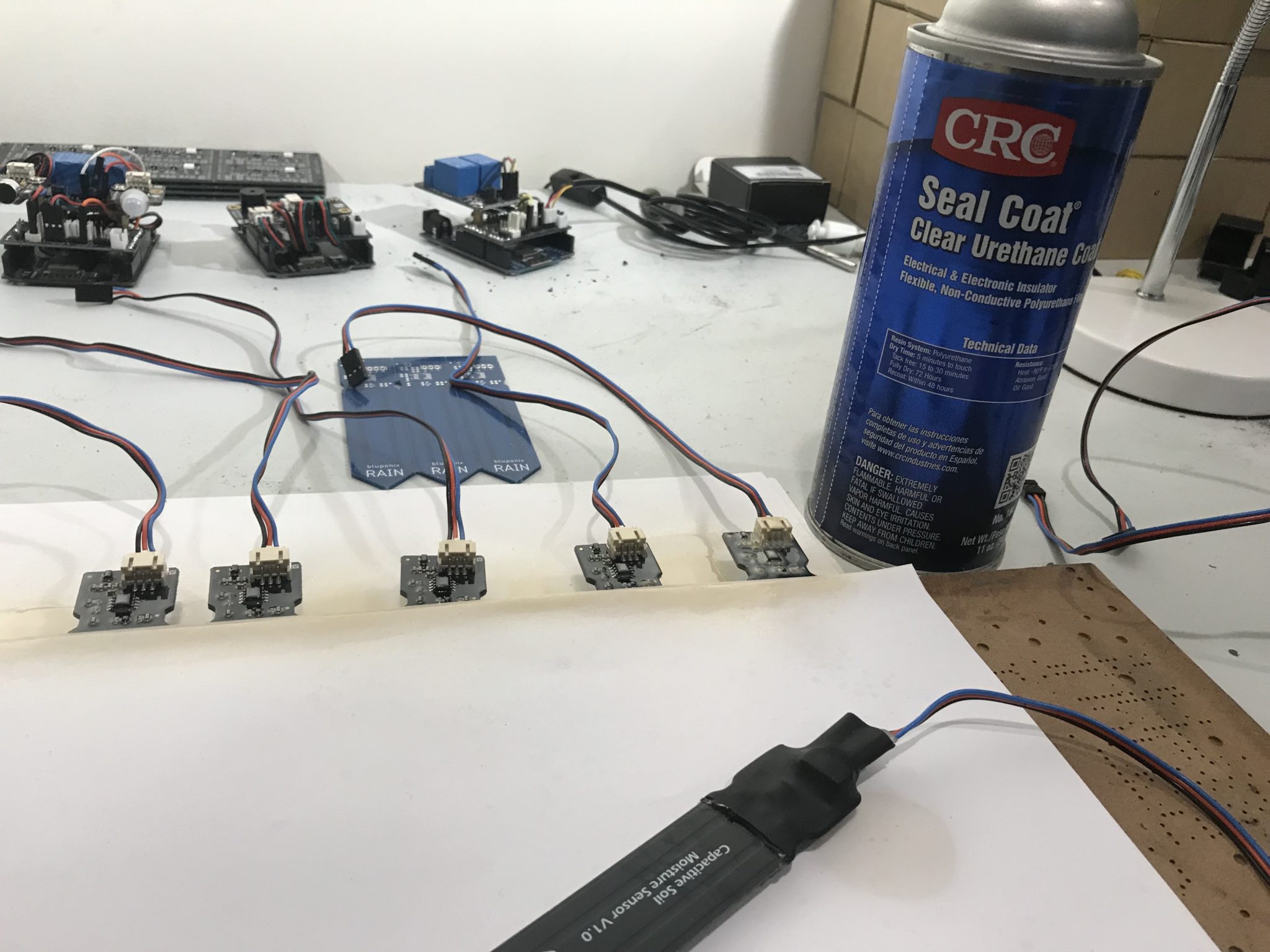
Capacitive Analog Soil Moisture Sensor with Connector
Prepare the Soil Moisture Sensor: The first step is to clean the moisture sensor with isopropyl alcohol. Next connect the analog PCB connector to the sensor. We will apply a clear urethane seal coat to protect and ultimately waterproof the components on the soil moisture sensor board. After snapping the board connector in place, place the sensor with components facing upward on top a piece of paper or cardboard. Next position a second piece of paper over the moisture sensor board covering the entire bottom of the board but leaving the board components exposed.
Coat the Soil Moisture Sensor PCB with Urethane Seal: Next, in a well-ventilated area, generously spray the first coat of clear urethane sealant over the soil moisture sensor components. Let the sensor dry for at least 30 minutes. Apply a second coat after the urethane seal dries to increase protection and let sit again for at least another 30 minutes. Next turn the sensor board over. Finally apply two separate coats of urethane sealant to the backside of the moisture sensor.
Apply a 3:1 Double Wall Adhesive-Lined Heat Shrink: Now place a strip of double walled adhesive lined heat shrink over the sensor components previously protected with a double coat of urethane sealant. Take a heat gun to heat up the heat shrink. Be sure to apply enough heat to melt the glue adhesive lining the heat shrink. This will ensure further waterproofing for your newly ruggedized soil moisture sensor. While still hot, firmly press the heat shrink together to seal the opening near the connector wires as shown in the video above.
Now you have ruggedized and waterproofed your analog soil moisture sensor.
You can also purchase this ruggedized and waterproof analog soil moisture sensor here in the Adosia IoT Store.
Follow these simple steps in the video above to make a DIY motion activated WiFi Stove Light. Here we setup the light so it can only be activated at night using the Adosia IoT platform. You can use this same tutorial to also build a WiFi night light.
Materials Needed to Make a DIY Motion Activated Stove Light:
aluminum LED strip channel and plastic channel cover
x2 magnets
x2 construction screws
x1 paired velcro strip
hacksaw or file
Part 1: Prepare the LED Channel
To prepare the LED channel you will first need to remove the plastic channel cover from the aluminum channel.
Now you can take a hacksaw or file to create a small notch on one edge located directly the center of the aluminum LED channel. This notch is where the LED strip wires will come through.
Next remove the strip of paper protection from the backs of both LED strips.
After that position the LED strips along the inside of the aluminum LED channel so the wires of both LED strip meet in the center of the strip as shown in the video.
Next simply place a screw at each end of the aluminum LED channel, and replace the plastic channel cover over the aluminum LED channel
Finally turn the aluminum LED channel over and place a magnet on the back of each opposing side along the inside of the aluminum channel. We use screws because they are magnetic and will allow the magnets to hold the weight of the aluminum (which is not magnetic) by attracting the screws.
Part 2: Mount the LED Channel and Adosia IoT Board
First press the opposing velcro strips together and remove the plastic from one of the strips.
Next attach the velcro strips to the back of your Adosia IoT Device. Remove the plastic from the other velcro strip. Now mount the Adosia IoT Device as desired by pressing if firmly against the wall with the sticky velcro strip exposed and in direct contact with the wall.
Now snap the LED strip channel to the bottom of the microwave located right over the stove.
Finally connect the LED strip to the Adosia IoT board (and motion detector if not already), power up your device, and then program it via the Adosia IoT Platform.
DIY Motion Activated Stove Light
DIY Motion Activated Nightlight
Alternatively, we can use a similar setup to create a DIY motion activated nightlight. All we need is an Adosia WiF controller, an LED light strip and something to house our light. In this example, we choose a hollow plastic pumpkin.
Materials Needed to Make a DIY Motion Activated Nightlight:
hollow plastic container or desired area to mount LED strips
All you need to do is cut a few holes out in your container for the lighting to exit, cut a hole for the power cord to come inside the container, place the device inside the container, power it up and program it at adosia.com.
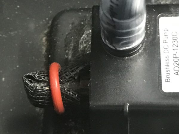
complete video tutorial for building a submersible water pump + water level sensor switch assembly to prevent pump from running dry and burning out
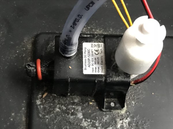
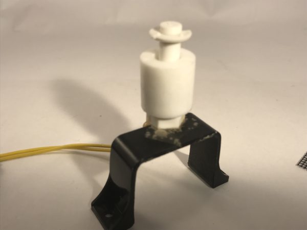
completed DIY submersible pump with level switch subassembly glued to bottom of the a water reservoir
Follow these steps to make a DIY submersible pump level switch assembly. A submersible water pump needs to be submersed in liquid because it will burn out if run dry. Here we will be attaching a water level sensor switch directly above a submersible water pump in order to protect the water pump. Above all we want to ensure the longest possible operational life of the pump. Positioning the level switch directly above the pump will prevent the pump from burning out by not allowing it to run while not fully submersed in water.
Materials Needed to Make a DIY Submersible Pump Level Switch Assembly:
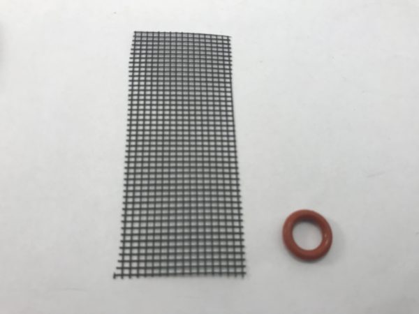
1 1/4″ x 2 1/2″ plastic screen for simple pump filter (optional)
Preparing the DIY submersible pump level switch assembly is simple and will only take around 5-10 minutes. The components you will need for this project are below.
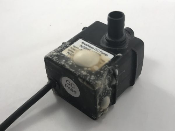
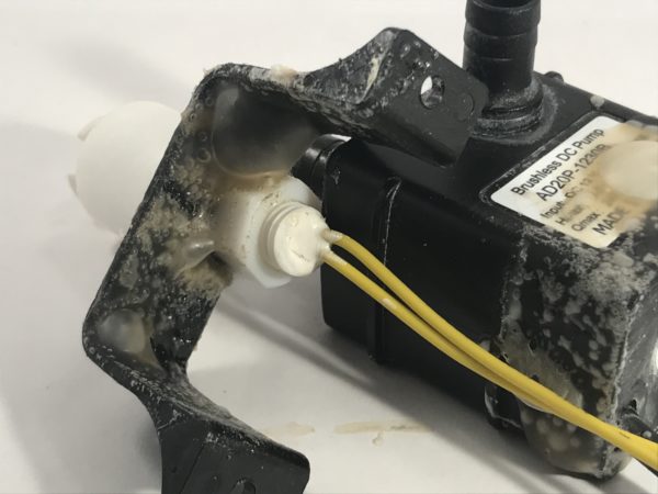
Step 1: Scuff the Surfaces of the Submersible Pump and Retaining Clip
use sandpaper to scuff the underside of the pump (when laying flat) where it will be glued to the reservoir floor
now scuff the three surrounding sides located at the rear of the pump towards the wiring as show below
notice sandpaper scuff all along the back edge
scuff with sandpaper all along the back edge
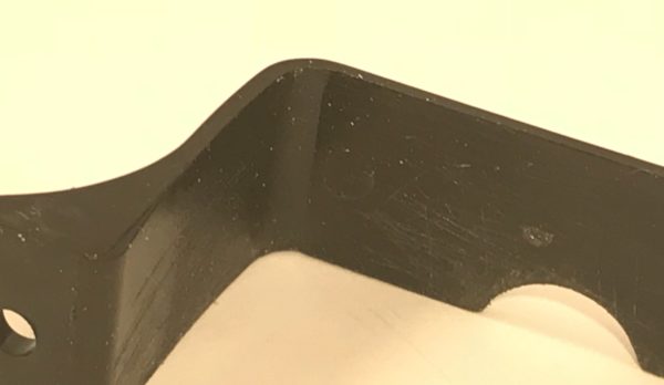
scruff the underside and top around the hole of the small plastic retaining mounting clip
notice scuffing along inside of small plastic mounting clip included with kit to secure pump
Step 2: Glue the Level Switch to the Pump Retaining Clip
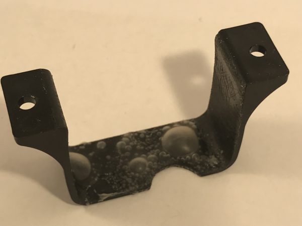
apply the 3M spray adhesive to the underside of the pump retaining clip mount and to the top around the semicircle hole as show below. Let stand for a few minutes as instructed by the glue canister
spray 3M adhesive glue around the top
spray 3M adhesive on the underside as shown
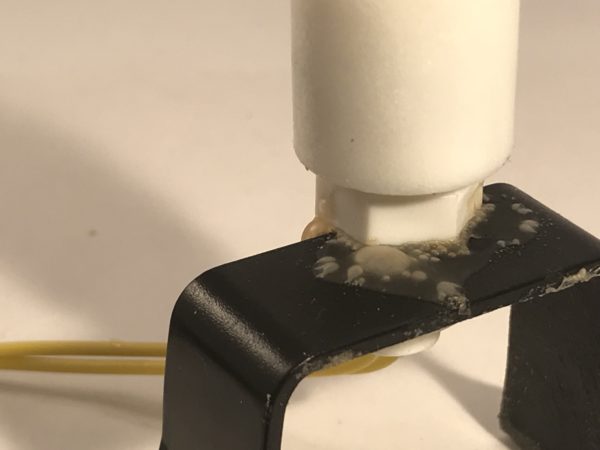
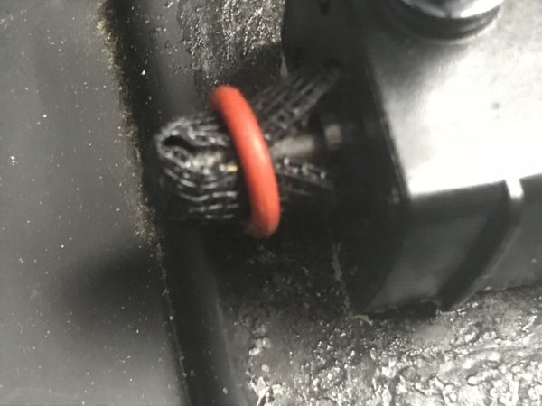
unscrew the plastic mounting nut on the base of the level sensor switch and remove the rubber o-ring and set it aside as we’ll use that later for an easy diy pump water intake filter
re-screw the plastic mounting nut onto the base of the level sensor switch just enough to slide over the thickness of the plastic pump retaining clip.
Spray the adhesive glue along the inside of the plastic mounting nut as show and let sit a few minutes
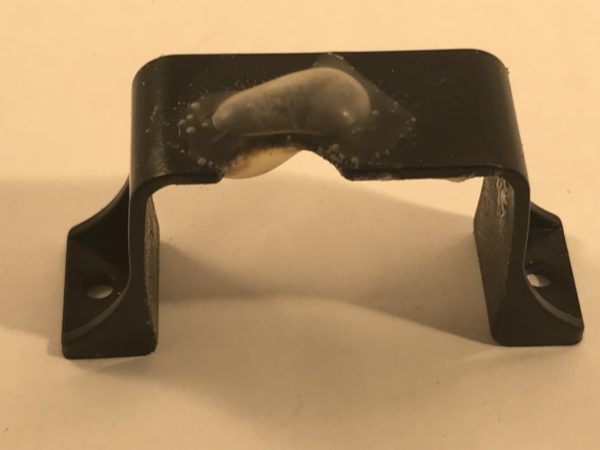
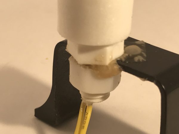
glue the water level sensor switch to the pump retaining clip mount
attach the water level sensor switch as shown
attach the water level sensor switch as shown
allow the bonding adhesive dry for 10-15 minutes to secure the level switch to the pump retaining clip
Step 3: Attach the Level Switch / Retaining Clip Assembly to the Water Pump
next with the pump laying flat, spray the 3M spray adhesive around the three exposed edges of towards the rear of the as shown below on the left
adhesive bond applied to rear sides of pump
adhesive bond applied to inside of retaining clip
spray the 3M adhesive around the inside edges of the retaining clip assembly as shown above right
allow the 3M bonding adhesive to rest for about a minute before attaching the level switch to the water pump
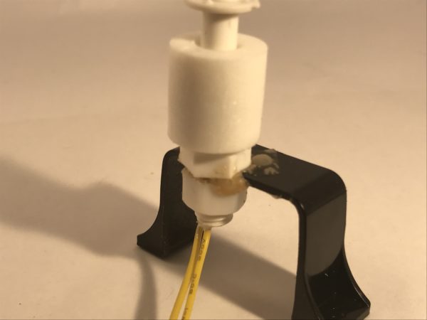
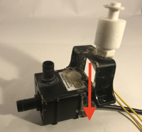
attach the level switch assembly to the water pump by sliding the level switch pump retaining clip assembly down the rear of the pump as shown below
attaching the water level sensor switch assembly to the water pump
allow the bonding adhesive dry for 10-15 minutes in order to secure the level switch assembly to the water pump
Step 4: Attach a Screen Filter to the Water Pump (optional)
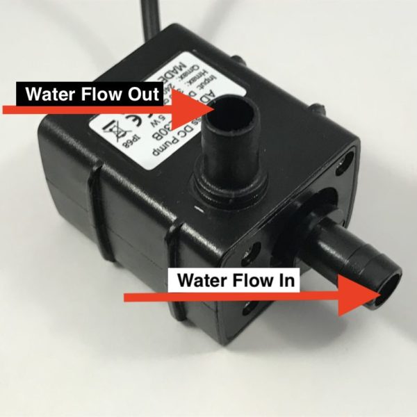
spray the 3M adhesive around the rim of the pump intake (where water flows in) and let set a minute
apply 3M adhesive around the outer rim of the water intake (flow in)
fold the plastic screen in half and then fold it over the water intake of the pump as shown below, and then secure the screen in place with the rubber o-ring taken from the water level sensor switch – let dry for 10-15
plastic screen cutting (1-1/4″ x 2-1/2″)
adhesive bond applied to inside of retaining clip
Step 5: Attach the Watering Tube to the Submersible Pump
It’s best to attach the watering tube to the DIY submersible pump level switch assembly before the assembly is glued to the bottom a reservoir in order to prevent the assembly from detaching from the base of the reservoir after it has been securely glued down.
attach the 1/4″ inner diameter tubing firmly to the top of the pump as shown below
tubing (1/4″ inner diameter) attached to the top of the water pump
Step 6: Install the Pump Level Switch Assembly to a Reservoir
Finally you can complete the DIY submersible water pump with level switch assembly installation by gluing it to the bottom of a reservoir.
Follow these simple steps to make a DIY self watering pot or planter to water plants automatically and help keep your plants alive year round with little to no maintenance.
1 1/4″ x 2 1/2″ plastic screen for simple pump filter (optional)
plastic enclosure from Adosia store with velcro strips (optional)
Step 1: Prepare the Soil Container & Water Reservoir
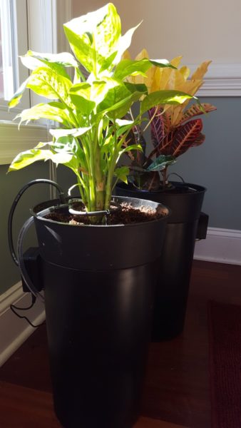
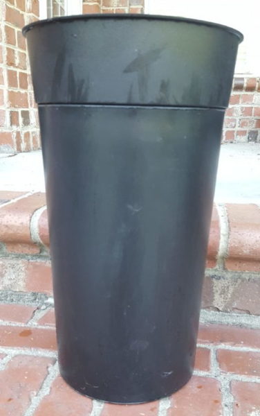
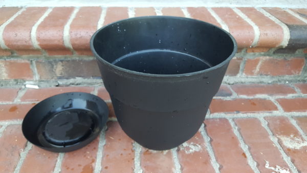
Finding the right container and reservoir is the first step in making your diy self watering pot. Here we use a 10″ standard garden pot for the soil container and a cylindrical 3L Sterilite trash can for the water reservoir. Both were purchased locally at Walmart for around $10 total. Discard any water collector disc that came with the pot along with any lid from the trash can as they will not be needed.
Place the soil container into the reservoir and observe how the container fits to rest sitting perfectly (bottom left image). Any planting container or reservoir can be used for your DIY self watering pot as long as the soil container is kept separate from the reservoir water. For the creative and daring, a wood planter box having the interior treated with a few coats of liquid rubber sealant would work nicely as well.
1a) prepare the soil container (garden pot):
drill a 3/8″ hole about with the center of the hole being about 1/2″ to 3/4″ down from the top of the upper rim of the potting container as shown in the image below:
arrow shows soil container drill hole location
1b) prepare the water reservoir (storage bin / trash can)
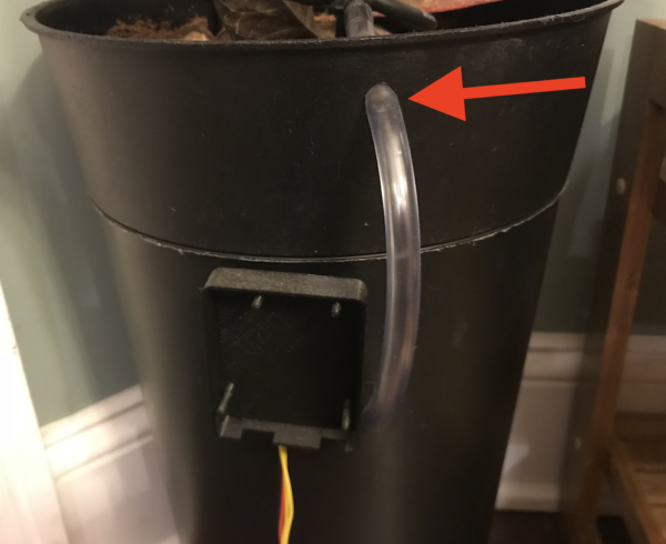
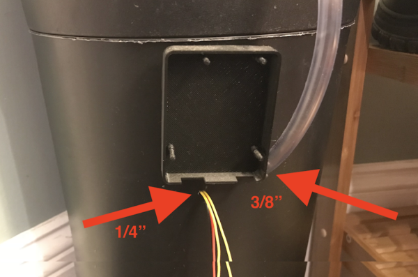
next drill another 3/8″ hole about 4″ down from the top of the reservoir. This is an exit hole for the water transport tubing connected to the pump inside the reservoir. The tubing should have a 1/4″ inner diameter which fits snugly to the submersible water pump.
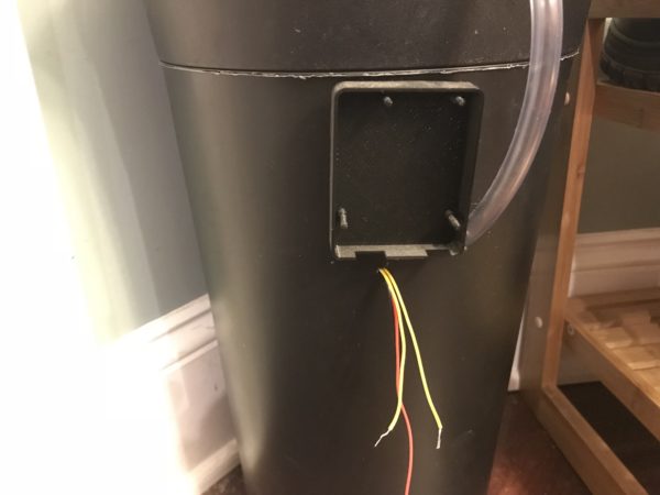
finally drill a 1/4″ hole in the reservoir container about an inch down and few inches to the left of the 3/8″ hole drilled in the last step. This hole needs to be located low enough so the wiring from the pump and water level sensor switch can extend from the reservoir bottom (where the pump will be located), to the electrical connectors on the control board.
arrows show the drill hole locations needed for the water reservoir
scuff the bottom of the reservoir lightly with sandpaper in a small area where the pump will be glued. This will help the pump bond better to the plastic reservoir
Step 2: Attach the Water Level Sensor Switch to the Pump
Preparing the submersible pump for installation into the reservoir of the diy self watering pot will take around 5-10 minutes. Before we glue the pump to the bottom of the water reservoir, we’ll first use sandpaper to scuff all the contact surface areas where we will be gluing plastic together. This enhances the bond between plastic parts when glued together.
We will also want to attach a water level sensor switch with the reservoir so it’s at an appropriate vertical height to trigger when the water level starts to get low. We also want to make sure to position the water level sensor switch at a vertical height above the pump to ensure enough water is always in the reservoir when the pump runs to prevent it from ever running dry.
In this example, we’ll be gluing the water level sensor switch to the reservoir. The components needed will look something like this.
2a) scuff plastic surfaces in preparation for application of glue
use sandpaper to scuff the underside of the pump (when laying flat) where it will be glued to the reservoir floor
now scuff the three surrounding sides located at the rear of the pump towards the wiring as show below
notice sandpaper scuff all along the back edge
scuff with sandpaper all along the back edge
scruff the underside and top around the hole of the small plastic retaining mounting clip
notice scuffing along inside of small plastic mounting clip included with kit to secure pump
2b) glue the water level sensor switch to plastic pump retaining clip mount
apply the 3M spray adhesive to the underside of the pump retaining clip mount and to the top around the semicircle hole as show below. Let stand for a few minutes as instructed by the glue canister
spray 3M adhesive glue around the top
spray 3M adhesive on the underside as shown
unscrew the plastic mounting nut on the base of the level sensor switch and remove the rubber o-ring and set it aside as we’ll use that later for an easy diy pump water intake filter
re-screw the plastic mounting nut onto the base of the level sensor switch just enough to slide over the thickness of the plastic pump retaining clip.
Spray the adhesive glue along the inside of the plastic mounting nut as show and let sit a few minutes
glue the water level sensor switch to the pump retaining clip mount
attach the water level sensor switch as shown
attach the water level sensor switch as shown
allow the bonding adhesive dry for 10-15 minutes to secure the level switch to the pump retaining clip
2c) attach the water level sensor switch / retaining clip assembly to the water pump
with the pump laying flat, spray the 3M spray adhesive around the three exposed edges of towards the rear of the as shown below on the left
adhesive bond applied to rear sides of pump
adhesive bond applied to inside of retaining clip
spray the 3M adhesive around the inside edges of the retaining clip assembly as shown above right
allow the 3M bonding adhesive to rest for about a minute before attaching the level switch to the water pump
attach the level switch assembly to the water pump by sliding the level switch pump retaining clip assembly down the rear of the pump as shown below
attaching the water level sensor switch assembly to the water pump
allow the bonding adhesive dry for 10-15 minutes to secure the level switch assembly to the water pump
2d) attach a screen filter to the pump (optional but recommended)
spray the 3M adhesive around the rim of the pump intake (where water flows in) and let set a minute
apply 3M adhesive around the outer rim of the water intake (flow in)
fold the plastic screen in half and then fold it over the water intake of the pump as shown below, and then secure the screen in place with the rubber o-ring taken from the water level sensor switch – let dry for 10-15
plastic screen cutting (1-1/4″ x 2-1/2″)
adhesive bond applied to inside of retaining clip
2e) attach the watering tube to the submersible pump
attach the 1/4″ inner diameter tubing firmly to the top of the pump as shown below
tubing (1/4″ inner diameter) attached to the top of the water pump
Step 3: Complete the DIY Self Watering Pot Reservoir
First we will glue the pump to the bottom of the reservoir, and then pull both the water tubing and wiring through their respective drill holes to the outside of the reservoir
3a) glue the pump to the bottom of the water reservoir
spray the 3M bonding adhesive on the bottom of the pump and on the bottom of the reservoir where both were previously scuffed with sandpaper and let sit for a minute or two
press the pump down firmly onto the floor of there reservoir and let set to dry for about 20 minutes – it may help to place something on top of the pump to keep it flush with the reservoir bottom while the bonding adhesive dries
pump subassembly glued to bottom of the self watering pot reservoir
3b) pull the clear tubing and wiring through the reservoir drill holes
first pull the 3/8″ outer diameter tubing through the previously drilled 3/8″ hole to the outside of the water reservoir
next guide the pump and level switch wiring through the previously drilled 1/4″ hole to the outside of the reservoir
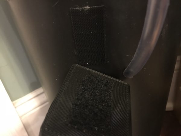
if you purchased an 3D plastic printed enclosure, adhere a fuzzy velcro strip to the back of the enclosure while adhering the prickly velcro strip to the upper side of the pot – attach the enclosure to the pot as shown below
wiring and water tube pulled to outside of pump
velcro strips adhered to the pot and enclosure
3c) ready the water reservoir and soil / medium container
first add water to the self watering pot reservoir to just below the lowest drill hole location in the pot
next add soil or desired grow medium to the upper soil / medium container – make sure to include your plant!
place the soil / medium container so it rests nicely on top of the water reservoir
Step 4: Connect the Electronics for the DIY Self Watering Pot
Now we connect the water level sensor switch, the pump, and the moisture sensor to the electronics control board.
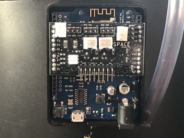
insert the Adosia electronics control board into the enclosure base attached to the side of the pot / soil container
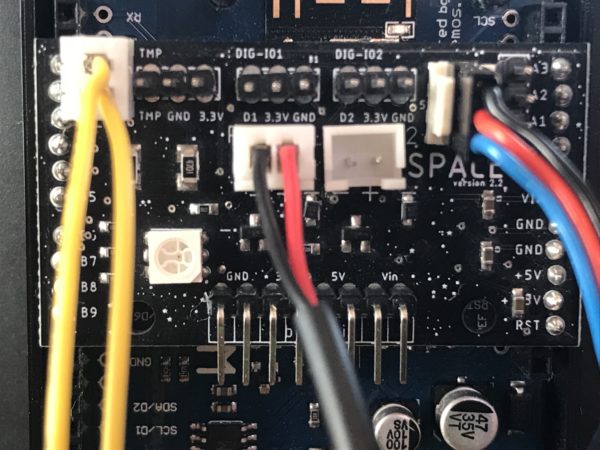
first connect the water level sensor switch (yellow wires) as show in the image below
next connect the submersible pump (black and red wire) as show in the image below
finally connect the soil moisture sensor (black, red and blue wires) as show in the image below – make sure the blue wire is oriented as shown below – the black wire should be closest to the top of the pot with the blue wire closest to the bottom
diy self watering pot electronics control board
level switch (l), pump (c), moisture sensor (r)
Step 5: Create the DIY Self Watering Pot Watering Ring
We now need to create and attach a watering ring to the clear tubing connected to the reservoir.
first guide the clear 3/8″ tubing through the top hole (in the soil / medium container) so it rests over the inside of pot / medium if you haven’t already done so
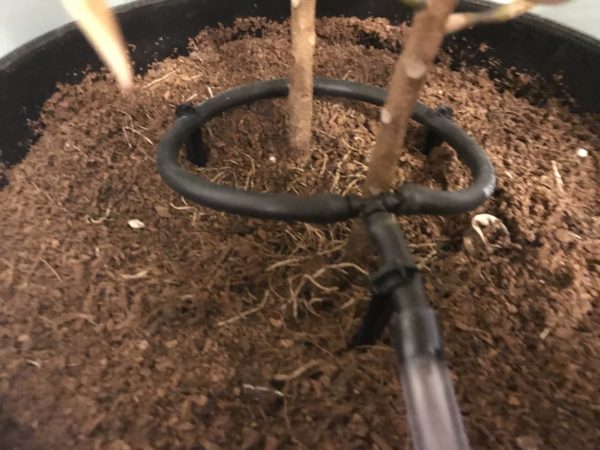
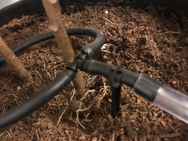
now create a watering ring of your choice – in this example we use black 1/4″ outer diameter landscaping tubing
next take a 2″ segment of landscaping tubing and connect it to the base of the tee-connector
now drill 4 to 5 small holes around the bottom of the remaining landscaping tube and connect both ends of the tube to the tee connecter (also included in kit) to make a ring
then forcefully insert the open end of the 2″ segment of the black landscaping tube (1/4″ outer diameter) into the clear tubing (3/8″ outer diameter / 1/4″ inner diameter) as show below
next secure the circular ring around the base of the plant using the tube stakes
diy self watering pot watering ring
diy self watering pot watering ring connection
Step 6: Complete the DIY Self Watering Pot
We can now complete our DIY self watering pot
first insert the soil moisture sensor into pot about 2-4″ from the nearest watering ring so soil around the sensor gets moist after about 10-30 seconds of watering depending on the operating mode you select
next plug the 12V A/C adapter end connector into the electronics control board
finally power up your DIY self-watering pot by plugging the A/C adapter into the wall
You DIY self-watering pot should begin watering immediately. The light on the control board will blink blue when the water reservoir is empty. The easiest way to refill the reservoir is to simple pour 1 to 2 gallons of water directly onto the base of the plant when needed.
Depending on the selected operating mode, your DIY self watering pot should be able to water without needed to be refilled for about 1 to 3 months!